Triode Based RF Pulse Amplifier.
64 KW, 1250 – 1350 MHz.
DESCRIPTION: Two stage amplifier.
Each stage has a gain of 10 dB. Both stages are triode based. Circulators are installed between stages to minimize the effects of impedance mismatch. The loads are not meant to handle full reflected power. The first stage employs a single tuned input cavity and an over-coupled, double tuned output cavity to create a bandwidth of 100 MHz.
The final stage is a unique design with four triodes in a multimode resonator. The anodes of the amplifier tubes are connected to a multimode resonator where their outputs are combined. Correct phasing of the individual tubes is achieved by controlling the lengths of the interstage coax cables. A second multimode resonator is coupled to the first to form an over coupled, double tuned band-pass transformer. Output load matching is accomplished with a capacitive divider within the resonator.
| SPECIFICATIONS | |
|---|---|
| FREQUENCY | 1250 TO 1350 MHz |
| POWER OUTPUT | 64 KW PEAK |
| DYNAMIC RANGE | 40 dB |
| RF GAIN | 20 DB |
| GAIN VARIATION | +/- 1 dB BELOW 10 dB DOWN +1/-3 ABOVE 0 dB DOWN |
| SPURIOUS | -50 dBc IN BAND |
| HARMONICS | -30 dBc |
| IMPEDANCE INPUT & OUTPUT | 50 OHMS |
| INPUT VSWR | LESS THAN 1.5:1 |
| PULSE WIDTH | 1 TO 4 µSEC |
| DUTY CYCLE | .0035 |
| MODULATOR INPUT PULSE | 5 VOLTS |
| DIMENSIONS | 26″ x 29″ x 10″ |
The photograph above shows one of ten units built for the Mini-MUTES electronic warfare training system. It was designed to handle vibration and wide thermal swings. We use a unique output cavity design to broaden the band and a unique combiner to add up the output of multiple tubes. Each stage has 10dB of gain. More stages can be added to the input or the output side to increase the gain.
We are currently building a 100kW amplifier with 50dB of gain. Click for more details.
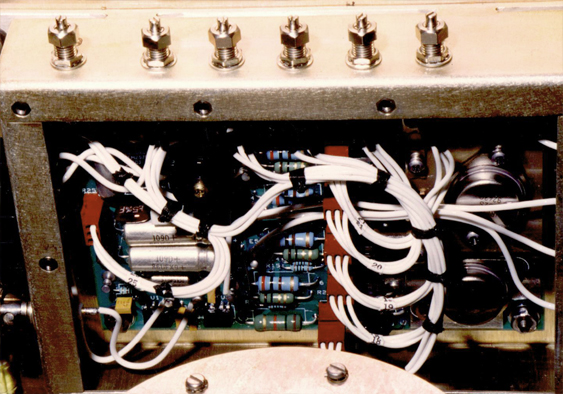
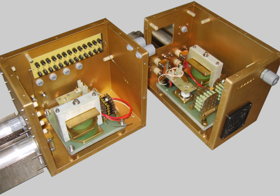
Bias Modulator
The bias modulator circuit is compact and adjustable to provide maximum linearity. Bias voltage is pulsed to completely shut off RF during the interpulse period.
Driver Cavities
Driver cavities can be chained together, 10dB gain each, for a practical input power of 5W and an output of up to 5kW.
The amplifiers are designed for maximum pulse widths in the 4µS range and duties in the 0.35% range.
Custom parts are produced by our in-house machine shop to exacting specifications.

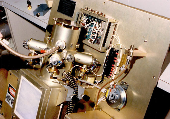
Final Combiner
Final combiners have 10 dB of gain each and they are also stackable for outputs from 10kW to 100kW. The stages are air cooled so there’s no need to worry about pumps, heat exchangers or a glycol mix. Pressure switches warn in case of air flow loss.
For turnkey systems we supply touch screen control that enables central monitoring of faults and power supplies. Systems can be run remotely through an Ethernet cable.
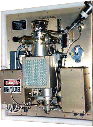
High Voltage Assembly
The high voltage assemblies are enclosed for safety. They are air filled rather than oil filled to keep them light and easy to access. They incorporate a crowbar to dump the energy in case of a tube arc.